EV manufacturer
Mercedes-Benz EV diagnostics
Browse in-scope 2021+ battery-electric and plug-in hybrid model families, plus evidence-labelled diagnostic records.
12 model families49 verified32 reference candidates
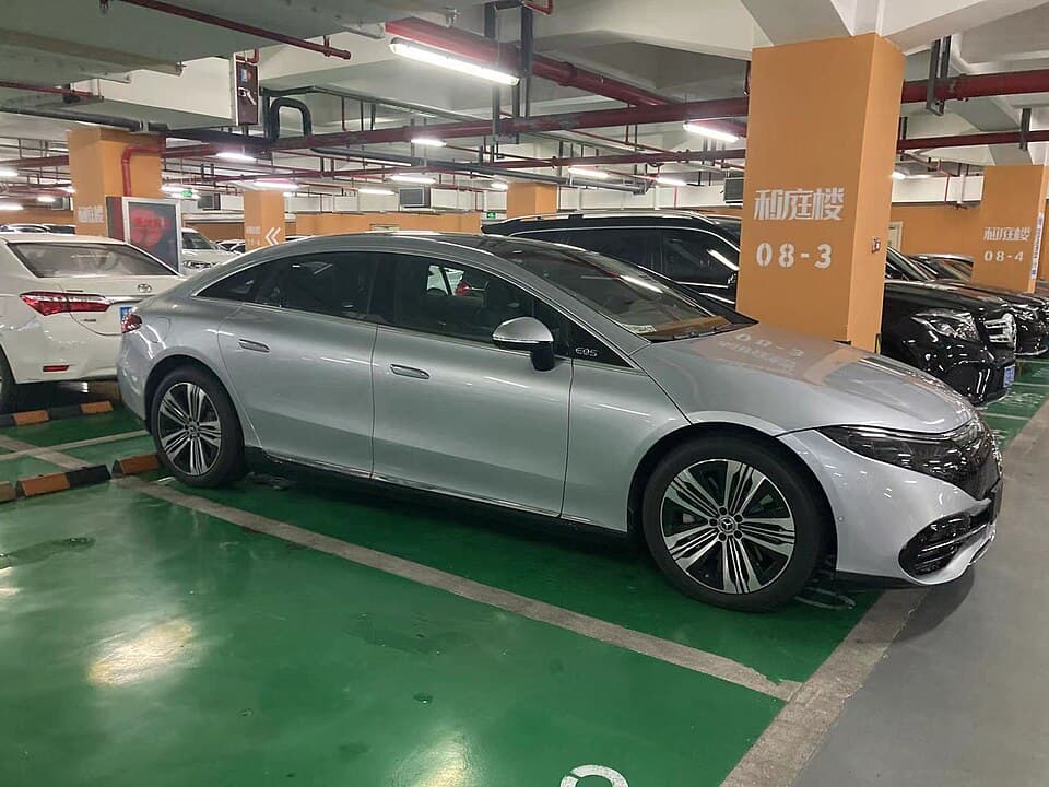 Mercedes-Benz EQS
Models
Mercedes-Benz AMG GT
PHEV · 2025
0 verified applicable recordsMercedes-Benz C-Class
PHEV · 2025
0 verified applicable recordsMercedes-Benz CLA-Class
BEV · 2026–2027
16 verified applicable recordsMercedes-Benz E-Class
PHEV · 2025–2026
0 verified applicable recordsMercedes-Benz EQB
BEV · 2022–2025
11 verified applicable recordsMercedes-Benz EQE
BEV · 2024–2027
16 verified applicable recordsMercedes-Benz EQS
BEV · 2022–2027
26 verified applicable recordsMercedes-Benz G-Class
BEV · 2025–2026
9 verified applicable recordsMercedes-Benz GLC-Class
PHEV · 2025
0 verified applicable recordsMercedes-Benz GLE-Class
PHEV · 2025
0 verified applicable recordsMercedes-Benz S-Class
PHEV · 2023–2025
0 verified applicable recordsMercedes-Benz SL-Class
PHEV · 2025
0 verified applicable recordsVerified Manufacturer-level verified records
These records passed the verified evidence gate. Model applicability is shown only where separately supported.
High -voltage electrical system faultHigh -voltage electrical system faultCooling system fault, operating en- ergy input reduced, service requiredCooling system fault, operating en- ergy input reduced, service requiredFC151E29- The level sensor at front left has a malfunction. There is an invalid si- gnalFC151E29- The level sensor at front left has a malfunction. There is an invalid si- gnalReduced Drive PowerReduced Drive PowerU05B7E1range radar sensor calibration drive as outlined in LI54.71-P-078377. If one or more unsuccessful programming or coding operation occurs – observe SI54.21-P-0067S. 3. Disconnect XEU05B8E1range radar sensor calibration drive as outlined in LI54.71-P-078377. If one or more unsuccessful programming or coding operation occurs – observe SI54.21-P-0067S. 3. Disconnect XEU05B5E1range radar sensor calibration drive as outlined in LI54.71-P-078377. If one or more unsuccessful programming or coding operation occurs – observe SI54.21-P-0067S. 3. Disconnect XEU05B6E1range radar sensor calibration drive as outlined in LI54.71-P-078377. If one or more unsuccessful programming or coding operation occurs – observe SI54.21-P-0067S. 3. Disconnect XEDriver Assistance System Func- tions Limited Please Drive with Caution See OperatorDriver Assistance System Func- tions Limited Please Drive with Caution See OperatorThe control unit has an internal hardware fault. The system function is restricted.The control unit has an internal hardware fault. The system function is restricted.There is an internal fault in the stee- ring angle sensor. There is an implausible signal.There is an internal fault in the stee- ring angle sensor. There is an implausible signal.Driver assistance systems function limitedDriver assistance systems function limitedErase fault memoryErase fault memorydriver assistance systems unavailabledriver assistance systems unavailableDigital Light: Functionality limitedDigital Light: Functionality limitedDriving assistance system function limitedDriving assistance system function limitedDIGITAL LIGHT reduced range of functionsDIGITAL LIGHT reduced range of functionsActive Emergency Stop Assist Currently UnavailableActive Emergency Stop Assist Currently UnavailableThe electric power steering has a malfunction. There is a component fault.The electric power steering has a malfunction. There is a component fault.The electric power steering has a malfunction. There is a runtime error.The electric power steering has a malfunction. There is a runtime error.DRIVE PILOT cannot be activated system currently unavailableDRIVE PILOT cannot be activated system currently unavailableB15CE00control unit for telematics services (HERMES)": • The message "SOS - service not activated" permanently lights up in the instrument cluster AND the actual value "Error when replaciB19B613Antenna 4 open load Cause Antenna amplifier Remedy Replace the antenna amplifierB19B313Antenna 1 open load • B19B413 - Antenna 2 open load • B19B513 - Antenna 3 open load • B19B613 - Antenna 4 open load Cause Antenna amplifier Remedy Replace the antenna amplifierB19B513Antenna 3 open load • B19B613 - Antenna 4 open load Cause Antenna amplifier Remedy Replace the antenna amplifierB19B413Antenna 2 open load • B19B513 - Antenna 3 open load • B19B613 - Antenna 4 open load Cause Antenna amplifier Remedy Replace the antenna amplifierU142791"Implausible data were received from the control unit 'Head unit'. The parameter is outside the permissible range." Cause Under Determination. Remedy Update vehicle software to MBU0420E2SYS_EPS_22 • U041629 with error ID: SIG_ESP_12 • U013187 • U044229 Cause Software status of IDC_GEN6 In some cases, a diagnosis session or a software update may generate fault codeU041629SIG_ESP_12 • U013187 • U044229 Cause Software status of IDC_GEN6 In some cases, a diagnosis session or a software update may generate fault codes that do not cause any restrictionsB15BF00SIG_SEMA_C_22 • U0420E2 with error ID: SYS_EPS_22 • U041629 with error ID: SIG_ESP_12 • U013187 • U044229 Cause Software status of IDC_GEN6 In some cases, a diagnosis session or aC1016E0SIG_ESP_71 • B15BF00 with error ID: SIG_SEMA_C_22 • U0420E2 with error ID: SYS_EPS_22 • U041629 with error ID: SIG_ESP_12 • U013187 • U044229 Cause Software status of IDC_GEN6 In sU044229• All driver assist functions operate without restrictions AND • There are no persistent driver assist cluster messages (Example: white message for "Driver Assist SU013187• All driver assist functions operate without restrictions AND • There are no persistent driver assist cluster messages (Example: white message for "DriveP1CA000As a consequence, on vehicles with BMS30EB02, the DTC for the auxiliary assembly fuse P0E2F00 can be set. This triggers the yellow HV drive system warning message. In the ignitionP0E2F00board electrical system. This means the 12 V battery may be discharged in the event of longer use. Cause In individual ignition cycles, this may result in fauP0E5400As a consequence, on vehicles with BMS30EB02, the DTC for the auxiliary assembly fuse P0E2F00 can be set. This triggers the yellow HV drive system warning message. In the ignitionP0C3B00As a consequence, on vehicles with BMS30EB02, the DTC for the auxiliary assembly fuse P0E2F00 can be set. This triggers the yellow HV drive system warning message. In the ignitionU011500As a consequence, on vehicles with BMS30EB02, the DTC for the auxiliary assembly fuse P0E2F00 can be set. This triggers the yellow HV drive system warning message. In the ignitionP1D0B00As a consequence, on vehicles with BMS30EB02, the DTC for the auxiliary assembly fuse P0E2F00 can be set. This triggers the yellow HV drive system warning message. In the ignitionP0C4000As a consequence, on vehicles with BMS30EB02, the DTC for the auxiliary assembly fuse P0E2F00 can be set. This triggers the yellow HV drive system warning message. In the ignitionP0E9700As a consequence, on vehicles with BMS30EB02, the DTC for the auxiliary assembly fuse P0E2F00 can be set. This triggers the yellow HV drive system warning message. In the ignitionU071286U042986, Implausible data were received from the steering column module. There is an incorrect signal. Please open a TIPS case to the Body/Chassis/Entertainment inboxC220564"There is an internal fault in the steering angle sensor. There is an implausible signal." In the quick test, there are also no other DTC's in other control units that point to orC156F00The signal values of the level sensors are implausible. Cause Physical layer wiring to the level control sensors B22/X. Remedy Check A108/2 and A108/3 for freeze frame data sectionU013281Communication with control unit "Suspension" has a malfunction. Incorrect data were received. C156F00 - The signal values of the level sensors are implausible. Cause Physical layerB161609Due to a reduction in resistance at the HV voltage divider, the DC/DC converter measures an incorrect HV voltage. Regulation of the 12 V output voltage is therefore unstable or turB17D249The "Adaptive interior lighting" control unit for the rear right roof has malfunctioned. There is an internal electrical fault. Cause Software in the control units E48/3-5. RemedyB17D149The "Adaptive interior lighting" control unit for the rear left roof has malfunctioned. There is an internal electrical fault. • E48/4 (Adaptive rear interior lamp, roof, center) /B17D349The "Adaptive interior lighting" control unit for the rear center roof has malfunctioned. There is an internal electrical fault. • E48/5 (Adaptive rear interior lamp, roof, right)
Reference Brand reference codes
Openly licensed reference definitions are discovery data, not proof of applicability to a particular Mercedes-Benz EV.
P1105Atmospheric Pressure Sensor In Control Module
P1220Fuel Quantity Actuator Y231
P1221CAN Communication ETC Or ETS Interrupted
P1222IFI Accelerator Pedal Position Sensor R252
P1223Fuel Rack Position Sensor Y2311
P1335CKP Sensor IFI
P1350Injection Sensor Solenoid
P1351Injection Sensor Circuit
P1352Needle Lift Sensor
P1401EGR Lifting Sender B283
P1404EGR Control
P1465EPW Power
P1470Pressure Control Flap Vacuum Transducer Y312
P1475Resonance Intake Line Switchover Valve Y227
P1476Resonance Intake Manifold Switchover Valve Y226
P1480Preglow Control
P1481Glow Plug Failure
P1482Preglow Control Module N142
P1520Cruise Control Switch S40
P1610Voltage Supply Missing Or Relay Module K40
P1611IFI Control Module N37
P1612IFI Control Module N37 Voltage Circuit 15
P1613IFI Control Module N37
P1614IFI Control Module N37 Voltage Or Fuel Metering Actuator Y231K1 Or Fuel Rack Position Sensor Y2311
P1615IFI Control Module N37 Supply Voltage
P1617Control Module Fault Or Control Module Not Coded
P1622Electrohydraulic Shut-Off Actuator Y11
P1625Check Engine MIL
P1630Drive Authorization Signal
P1705Starter Lock-Out Backup Lamp Switch S161
P1780Modulation Pressure Switchover Valve ATCC Y34 Or Upshift Delay Switchover Valve ATCC Y35
P1781Upshift Delay Switchover Valve ATCC Y35