EV manufacturer
Mitsubishi EV diagnostics
Browse in-scope 2021+ battery-electric and plug-in hybrid model families, plus evidence-labelled diagnostic records.
1 model family213 verified33 reference candidates
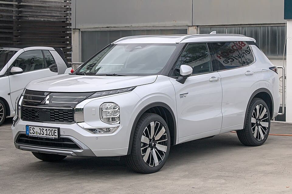 Mitsubishi Outlander PHEV
Models
Verified Manufacturer-level verified records
These records passed the verified evidence gate. Model applicability is shown only where separately supported.
C0065ion Battery in 2012 - 2013 model year i-MiEV vehicles are covered for defects in material and workmanship for 8 years or 100,000 miles (160,000km), whichever comes first. In the evP1A2F/C0068Print (and save) an “All DTC List.” /C0068Open a Techline case, and attach the DTC List to the Techline case. Click on the paper clip icon to attach files. /C0068Call TechLinU1111MEDIC must remain connected during the cell smoothing procedure (approximately 2 hours). Ensure MEDIC is fully charged or connected to a charging cable. 1. Turn the electric motorP1A4B/C0068Print (and save) an “All DTC List.” /C0068Open a Techline case, and attach the DTC List to the Techline case. Click on the paper clip icon to attach files. /C0068Call TechLinU1116MEDIC must remain connected during the cell smoothing procedure (approximately 2 hours). Ensure MEDIC is fully charged or connected to a charging cable. 1. Turn the electric motorC1931“Sensor failed.” NOTE: Photos must be posted on the PRC before entering the related Warranty claim. MMNA will issue a Warranty Parts Return Request for all replaced (Mirage) TPMS sC1512TORQUE SENSOR MAIN/SUB VOLTAGE FOUND IN EPS — 2015-16 Outlander Sport/RVR. In case you find DTC C1512 in the Electric Power Steering (EPS), obtain and attach Freeze Frame Data (FFDB142852B-004 Please make the indicated changes to the 2016 and 2017 i-MiEV Service Manual, Group 52B - Supplemental Restraint System (SRS) -> SRS Air Bag Diagnosis -> Diagnostic TroubleB143852B-004B141752B-004 See next page Page 12 of 22 TSB-18-52B-004 Page 13 of 22 TSB-18-52B-004 Please make the indicated changes to the 2016 and 2017 i-MiEV Service Manual, Group 52B - SupplementB143652B-004 Please make the indicated changes to the 2016 and 2017 i-MiEV Service Manual, Group 52B - Supplemental Restraint System (SRS) -> SRS Air Bag Diagnosis -> Diagnostic TroubleB142952B-004 Please make the indicated changes to the 2016 and 2017 i-MiEV Service Manual, Group 52B - Supplemental Restraint System (SRS) -> SRS Air Bag Diagnosis -> Diagnostic TroubleB142652B-004 Please make the indicated changes to the 2016 and 2017 i-MiEV Service Manual, Group 52B - Supplemental Restraint System (SRS) -> SRS Air Bag Diagnosis -> Diagnostic TroubleB140852B-004 Page 10 of 22 TSB-18-52B-004 Please make the indicated changes to the 2016 and 2017 i-MiEV Service Manual, Group 52B - Supplemental Restraint System (SRS) -> SRS Air Bag DiB143752B-004 Page 21 of 22 TSB-18-52B-004 Please make the indicated changes to the 2016 and 2017 i-MiEV Service Manual, Group 52B - Supplemental Restraint System (SRS) -> SRS Air Bag DiB141852B-004 Page 15 of 22 TSB-18-52B-004 Please make the indicated changes to the 2016 and 2017 i-MiEV Service Manual, Group 52B - Supplemental Restraint System (SRS) -> SRS Air Bag DiB143952B-004B141652B-004 Please make the indicated changes to the 2016 and 2017 i-MiEV Service Manual, Group 52B - Supplemental Restraint System (SRS) -> SRS Air Bag Diagnosis -> Diagnostic TroubleB142752B-004 Page 18 of 22 TSB-18-52B-004 Please make the indicated changes to the 2016 and 2017 i-MiEV Service Manual, Group 52B - Supplemental Restraint System (SRS) -> SRS Air Bag DiB140752B-004 Page 8 of 22 TSB-18-52B-004 Please make the indicated changes to the 2016 and 2017 i-MiEV Service Manual, Group 52B - Supplemental Restraint System (SRS) -> SRS Air Bag DiaB140652B-004 Please make the indicated changes to the 2016 and 2017 i-MiEV Service Manual, Group 52B - Supplemental Restraint System (SRS) -> SRS Air Bag Diagnosis -> Diagnostic TroubleB140952B-004 Page 10 of 22 TSB-18-52B-004 Please make the indicated changes to the 2016 and 2017 i-MiEV Service Manual, Group 52B - Supplemental Restraint System (SRS) -> SRS Air Bag DiB141952B-004 Page 15 of 22 TSB-18-52B-004 Please make the indicated changes to the 2016 and 2017 i-MiEV Service Manual, Group 52B - Supplemental Restraint System (SRS) -> SRS Air Bag DiP1A68CMU11 battery cell high voltage abnormal, P1A69: CMU12 battery cell high voltage abnormal . TROUBLE JUDGMENT Check Conditions Three seconds elapse after the electric motor switchU11A1CMU02 time-out, U11A2: CMU03 time-out, U11A3: CMU04 time-out, U11A4: CMU05 time-out, U11A5: CMU06 time-out, U11A6: CMU07 time-out, U11A7: CMU08 time-out, U11A8: CMU09 time-out, U11U11A8CMU09 time-out, U11A9: CMU10 time-out, U11AA: CMU11 time-out, U11AB: CMU12 time-out . M S B - 1 7 M 5 4 _ 5 5 - 0 0 1 ( 1 7 A B 0 3 7 ) 1 6 1 BATTERY MANAGEMENT UNIT (BMU) AND MAINP1A31ECU. Q: Is the diagnostic trouble code stored? YES : Carry out troubleshooting for diagnostic trouble code No. P1A3 0, P1A31 or P1B33. NO : Go to Step 2. STEP 2. Scan tool MB991958P1A42Power supply circuit of Main Drive Lithium-ion Battery current sensor abnormal b. P1A40: Main Drive Lithium-ion Battery current sensor (high) a bnormal c. P1A41: Main Drive LithiumP1AFAReturn to Step 1. NO : The diagnosis is complete. DTC P1AFB Quick charging time time-out CAUTION If there is any problem in the CAN bus lines, an incorrect DTC may be stored. PriorP0A0DReturn to Step 1. NO : The diagnosis is complete. M S B - 1 7 M 5 4 _ 5 5 - 0 0 1 ( 1 7 A B 0 3 7 ) 7 5 BATTERY MANAGEMENT UNIT (BMU) AND MAIN DRIVE LITHIUM-ION BATTERY TSB RevisioP1A74CMU11 module temperature abnormal (high input), P1A75: CMU12 module temperature abnormal (high input) . TROUBLE JUDGMENT Check Conditions Three seconds elapse after the electricP1A94CMU07 balancer abnormal, P1A95: CMU08 balancer abnormal, P1A96: CMU09 balancer abnormal, P1A97: CMU10 balancer abnormal, P1A98: CMU11 balancer abnormal, P1A99: CMU12 balancer abnorP1A95CMU08 balancer abnormal, P1A96: CMU09 balancer abnormal, P1A97: CMU10 balancer abnormal, P1A98: CMU11 balancer abnormal, P1A99: CMU12 balancer abnormal . M S B - 1 7 M 5 4 _ 5 5 -P1AA9Cell number mismatch . TROUBLE JUDGMENT Check Conditions When the CMUs are numbered for identification. The following diagnostic trouble codes is stored at the same time. a. U1P1A17Return to Step 1. NO : The diagnosis is complete. DTC P1AFA Quick charger READY timeout DTC P1AFE Quick charger error DTC P1AFF Quick charge port lock error DTC P1B00 Quick charU11A7CMU08 time-out, U11A8: CMU09 time-out, U11A9: CMU10 time-out, U11AA: CMU11 time-out, U11AB: CMU12 time-out . M S B - 1 7 M 5 4 _ 5 5 - 0 0 1 ( 1 7 A B 0 3 7 ) 1 6 1 BATTERY MANAGEMP1B00ECU. (1) Erase the stored DTC. (2) Connect the quick charging connector to charg e the battery fully. (3) Check if the DTC is stored. Q: Is the DTC stored? YES <DTC P1AFA> : Go toP1AA4CMU ID change (CMU10), P1AA5: CMU ID change (CMU11), P1AA6: CMU ID change (CMU12), . TROUBLE JUDGMENT Check Conditions When the CMUs are numbered for identification. Either oneP1B01Return to Step 1. NO : The diagnosis is complete. DTC P1B04 Maximum cell voltage abnormality during charging DTC P1B05 Minimum cell voltage abnormality during charging DTC P1B07U11A4CMU05 time-out, U11A5: CMU06 time-out, U11A6: CMU07 time-out, U11A7: CMU08 time-out, U11A8: CMU09 time-out, U11A9: CMU10 time-out, U11AA: CMU11 time-out, U11AB: CMU12 time-out . MP1A44Detecting Ground Fault . TROUBLE JUDGMENT Check Conditions 3.5 seconds elapse after the electric motor switch is turned ON, or 2 seconds elapse after the traction battery startsP0ADFReturn to Step 1. NO : The diagnosis is complete. DTC P0AE2 Charging contactor (seizure) DANGER When servicing the high voltage system parts, always shut off the high voltage byU11A5CMU06 time-out, U11A6: CMU07 time-out, U11A7: CMU08 time-out, U11A8: CMU09 time-out, U11A9: CMU10 time-out, U11AA: CMU11 time-out, U11AB: CMU12 time-out . M S B - 1 7 M 5 4 _ 5 5 -P1A41Main Drive Lithium-ion Battery current sensor (low) abnormal J udgment Criterion The output voltage of the Main Drive Lithium-ion Battery curr ent sensor (high) is less than 0.3U1925CMU ID numbering reception error . TROUBLE JUDGMENT Check Conditions When the CMUs are numbered for identification. ACC07057 C-21 (GR) AQ CMU01 to 05 (B) CMU07 CMU06 CMU12 CMU08P1AFDReturn to Step 1. NO : The diagnosis is complete. DTC P1B01 Quick charged vehicle error . OPERATIONS The quick charging plug communicates with the EV-ECU via the lo cal CAN (forP1A91CMU04 balancer abnormal, P1A92: CMU05 balancer abnormal, P1A93: CMU06 balancer abnormal, P1A94: CMU07 balancer abnormal, P1A95: CMU08 balancer abnormal, P1A96: CMU09 balancer abnorU11A6CMU07 time-out, U11A7: CMU08 time-out, U11A8: CMU09 time-out, U11A9: CMU10 time-out, U11AA: CMU11 time-out, U11AB: CMU12 time-out . M S B - 1 7 M 5 4 _ 5 5 - 0 0 1 ( 1 7 A B 0 3 7P0ADBReturn to Step 1. NO : The diagnosis is complete. DTC P0AE2 Charging contactor (seizure) DANGER When servicing the high voltage system parts, always shut off the high voltage byP1A8ECMU01 balancer abnormal, P1A8F: CMU02 balancer abnormal, P1A90: CMU03 balancer abnormal, P1A91: CMU04 balancer abnormal, P1A92: CMU05 balancer abnormal, P1A93: CMU06 balancer abnorP1A8FCMU02 balancer abnormal, P1A90: CMU03 balancer abnormal, P1A91: CMU04 balancer abnormal, P1A92: CMU05 balancer abnormal, P1A93: CMU06 balancer abnormal, P1A94: CMU07 balancer abnorP1A22ECU. Q: Is the DTC stored? YES : Carry out troubleshooting for the EV-ECU. Then go to Ste p 2. NO : Go to Step 2. STEP 2. Use scan tool MB991958, check freeze frame (FFD) data ChecP1AA3CMU ID change (CMU09), P1AA4: CMU ID change (CMU10), P1AA5: CMU ID change (CMU11), P1AA6: CMU ID change (CMU12), . TROUBLE JUDGMENT Check Conditions When the CMUs are numbered foP0AE6Return to Step 1. NO : The diagnosis is complete. DTC P1A15 High-voltage system error (1) DANGER When servicing the high voltage system parts, always shut off the high voltage byP1AABIs the diagnostic trouble code stored? YES : Replace the Main Drive Lithium-ion Battery. NO : The diagnosis is complete. Code No. P1AB5: CMU01 module temperature abnormal (low inpuP1A69CMU12 battery cell high voltage abnormal . TROUBLE JUDGMENT Check Conditions Three seconds elapse after the electric motor switch is turned ON, or three seconds elapse after theP1AFEECU. (1) Erase the stored DTC. (2) Connect the quick charging connector to charg e the battery fully. (3) Check if the DTC is stored. Q: Is the DTC stored? YES <DTC P1AFA> : Go toP1A8DCMU12 module temperature sensor abnormal . TROUBLE JUDGMENT Check Conditions Three seconds elapse after the electric motor switch is turned ON, o r three seconds elapse after theU11A9CMU10 time-out, U11AA: CMU11 time-out, U11AB: CMU12 time-out . M S B - 1 7 M 5 4 _ 5 5 - 0 0 1 ( 1 7 A B 0 3 7 ) 1 6 1 BATTERY MANAGEMENT UNIT (BMU) AND MAIN DRIVE LITHIUM-ION BATTP1A30ECU. Q: Is the diagnostic trouble code stored? YES : Carry out troubleshooting for diagnostic trouble code No. P1A3 0, P1A31 or P1B33. NO : Go to Step 2. STEP 2. Scan tool MB991958P1A96CMU09 balancer abnormal, P1A97: CMU10 balancer abnormal, P1A98: CMU11 balancer abnormal, P1A99: CMU12 balancer abnormal . M S B - 1 7 M 5 4 _ 5 5 - 0 0 1 ( 1 7 A B 0 3 7 ) 1 3 5 BAP1AA8Local CAN (for Main Drive Lithium-ion Battery) signal time-ou t b. U1082: Local CAN (for Main Drive Lithium-ion Battery) bus off Judgment Criterion The module temperature is lessP1A9ACMU ID auto numbering error . TROUBLE JUDGMENT Check Conditions When the CMUs are numbered for identification. Either one of the following diagnostic trouble codes is not sto rP1AB9CMU05 module temperature abnormal (low input), P1ABA: CMU06 module temperature abnormal (low input), P1ABB: CMU07 module temperature abnormal (low input), P1ABC: CMU08 module tempeP1A8CCMU11 module temperature sensor abnormal, P1A8D: CMU12 module temperature sensor abnormal . TROUBLE JUDGMENT Check Conditions Three seconds elapse after the electric motor switchP1A33ECU. Q: Is the diagnostic trouble code stored? YES : Carry out troubleshooting for diagnostic trouble code No. P1A3 0, P1A31 or P1B33. NO : Go to Step 2. STEP 2. Scan tool MB991958P1A90CMU03 balancer abnormal, P1A91: CMU04 balancer abnormal, P1A92: CMU05 balancer abnormal, P1A93: CMU06 balancer abnormal, P1A94: CMU07 balancer abnormal, P1A95: CMU08 balancer abnorP0AA1ECU. Q: Is the DTC stored? YES : Carry out troubleshooting for the DTC. NO : Go to Step 4. STEP 4. Use scan tool MB991958 to confirm a DTC of other systems Check if the DTC is storP1AA0CMU ID change (CMU06), P1AA1: CMU ID change (CMU07), P1AA2: CMU ID change (CMU08), P1AA3: CMU ID change (CMU09), P1AA4: CMU ID change (CMU10), P1AA5: CMU ID change (CMU11), P1AA6:P1B07Return to Step 1. NO : The diagnosis is complete. DTC P1B06 Maximum cell temperature abnormality during charging CAUTION If there is any problem in the CAN bus lines, an incorrectP1AB6CMU02 module temperature abnormal (low input), P1AB7: CMU03 module temperature abnormal (low input), P1AB8: CMU04 module temperature abnormal (low input), P1AB9: CMU05 module tempeP1B30ECU. Q: Is the diagnostic trouble code stored? YES : If diagnostic trouble code No. P1B30 is stored in the EV-ECU, replace the BMU. NO : If no diagnostic trouble code No. P1B30 isP1A83CMU02 module temperature sensor abnormal, P1A84: CMU03 module temperature sensor abnormal, P1A85: CMU04 module temperature sensor abnormal, P1A86: CMU05 module temperature sensor aP1B05Return to Step 1. NO : The diagnosis is complete. DTC P1B06 Maximum cell temperature abnormality during charging CAUTION If there is any problem in the CAN bus lines, an incorrectP1AA6CMU ID change (CMU12), . TROUBLE JUDGMENT Check Conditions When the CMUs are numbered for identification. Either one of the following diagnostic trouble codes is not sto red. aP1B06Return to Step 1. NO : The diagnosis is complete. DTC P1B0C On board charging current error (overcurrent) DTC P1B21 On board charger output current error CAUTION If there is any pU11A3CMU04 time-out, U11A4: CMU05 time-out, U11A5: CMU06 time-out, U11A6: CMU07 time-out, U11A7: CMU08 time-out, U11A8: CMU09 time-out, U11A9: CMU10 time-out, U11AA: CMU11 time-out, U11P1B33Go to Step 2. STEP 2. Scan tool MB991958 data list (1) Check the domestic power supply facility. (2) Connect the regular charging cable. (3) Check service data. Item No. 6: MinimP1A93CMU06 balancer abnormal, P1A94: CMU07 balancer abnormal, P1A95: CMU08 balancer abnormal, P1A96: CMU09 balancer abnormal, P1A97: CMU10 balancer abnormal, P1A98: CMU11 balancer abnorP1AA5CMU ID change (CMU11), P1AA6: CMU ID change (CMU12), . TROUBLE JUDGMENT Check Conditions When the CMUs are numbered for identification. Either one of the following diagnostic tP1A15ECU. Q: Is the DTC stored? YES : Carry out troubleshooting for the DTC. NO : Go to Step 4. STEP 4. High-voltage fuse No.1 (Main,280A) (Main Drive Lithium-ion Battery assembly) checP1A82CMU01 module temperature sensor abnormal, P1A83: CMU02 module temperature sensor abnormal, P1A84: CMU03 module temperature sensor abnormal, P1A85: CMU04 module temperature sensor aP1AB8CMU04 module temperature abnormal (low input), P1AB9: CMU05 module temperature abnormal (low input), P1ABA: CMU06 module temperature abnormal (low input), P1ABB: CMU07 module tempeP1AB7CMU03 module temperature abnormal (low input), P1AB8: CMU04 module temperature abnormal (low input), P1AB9: CMU05 module temperature abnormal (low input), P1ABA: CMU06 module tempeP1A92CMU05 balancer abnormal, P1A93: CMU06 balancer abnormal, P1A94: CMU07 balancer abnormal, P1A95: CMU08 balancer abnormal, P1A96: CMU09 balancer abnormal, P1A97: CMU10 balancer abnorP1A80CMU11 battery cell voltage sensor abnormal, P1A81: CMU12 battery cell voltage sensor abnormal . TROUBLE JUDGMENT Check Conditions Three seconds elapse after the electric motor swP0AE7Return to Step 1. NO : The diagnosis is complete. DTC P1A15 High-voltage system error (1) DANGER When servicing the high voltage system parts, always shut off the high voltage byP1AFBReplace the EV-ECU. Then go to Step 8. NO : The diagnosis is complete. STEP 8. Check whether the DTC is stored again Check again if the DTC is stored in the EV-ECU. (1) Erase the sP0AE2Return to Step 1. NO : The diagnosis is complete. M S B - 1 7 M 5 4 _ 5 5 - 0 0 1 ( 1 7 A B 0 3 7 ) 2 7 EV-ECU TSB Revision ELECTRIC MOTOR UNIT AND MAIN DRIVE LITHIUM-ION BATTERY54U11A0CMU01 time-out, U11A1: CMU02 time-out, U11A2: CMU03 time-out, U11A3: CMU04 time-out, U11A4: CMU05 time-out, U11A5: CMU06 time-out, U11A6: CMU07 time-out, U11A7: CMU08 time-out, U11P1A46Detection Circuit Of Traction Battery Ground Fault Detector Abnormal . TROUBLE JUDGMENT Check Conditions 3.5 seconds elapse after the electric motor switch is turned ON, or 2 secP1A81CMU12 battery cell voltage sensor abnormal . TROUBLE JUDGMENT Check Conditions Three seconds elapse after the electric motor switch is turned ON, or three seconds elapse after thP1A40Main Drive Lithium-ion Battery current sensor (high) a bnormal c. P1A41: Main Drive Lithium-ion Battery current sensor (low) abnormal J udgment Criterion The output voltage of thP1A16ECU. Q: Is the DTC stored? YES : Carry out troubleshooting for the DTC. NO : Go to Step 11. ACC07057 AE Harness side Charging contactor connector C-22 (GR) Intermediate connector (U11ABCMU12 time-out . M S B - 1 7 M 5 4 _ 5 5 - 0 0 1 ( 1 7 A B 0 3 7 ) 1 6 1 BATTERY MANAGEMENT UNIT (BMU) AND MAIN DRIVE LITHIUM-ION BATTERY TSB Revision ELECTRIC MOTOR UNIT AND MAINP1B21Return to Step 1. NO : The diagnosis is complete. DTC P1B0D Quick charging current error (overcurrent) CAUTION If there is any problem in the CAN bus lines, an incorrect DTC may beP1AA2CMU ID change (CMU08), P1AA3: CMU ID change (CMU09), P1AA4: CMU ID change (CMU10), P1AA5: CMU ID change (CMU11), P1AA6: CMU ID change (CMU12), . TROUBLE JUDGMENT Check Conditions P1A75CMU12 module temperature abnormal (high input) . TROUBLE JUDGMENT Check Conditions Three seconds elapse after the electric motor switch is turned ON, o r three seconds elapse aftP1AA1CMU ID change (CMU07), P1AA2: CMU ID change (CMU08), P1AA3: CMU ID change (CMU09), P1AA4: CMU ID change (CMU10), P1AA5: CMU ID change (CMU11), P1AA6: CMU ID change (CMU12), . TROUBU11A2CMU03 time-out, U11A3: CMU04 time-out, U11A4: CMU05 time-out, U11A5: CMU06 time-out, U11A6: CMU07 time-out, U11A7: CMU08 time-out, U11A8: CMU09 time-out, U11A9: CMU10 time-out, U11U1082Local CAN (for Main Drive Lithium-ion Battery) bus off Judgment Criterion For more than 3 seconds, one of the CMU signals cannot be received t hrough the CAN communication. . FAIU11AACMU11 time-out, U11AB: CMU12 time-out . M S B - 1 7 M 5 4 _ 5 5 - 0 0 1 ( 1 7 A B 0 3 7 ) 1 6 1 BATTERY MANAGEMENT UNIT (BMU) AND MAIN DRIVE LITHIUM-ION BATTERY TSB Revision ELECTRP1AF2ECU. Q: Is the DTC stored? YES : Carry out troubleshooting for the DTC. NO : Go to Step 4. STEP 4. Use scan tool MB991958 to confirm a DTC of other systems Check if the DTC is storP1A26ECU. Q: Is the DTC stored? YES : Carry out troubleshooting for the DTC. NO : Go to Step 11. ACC07057 AE Harness side Charging contactor connector C-22 (GR) Intermediate connector (P1B04Return to Step 1. NO : The diagnosis is complete. DTC P1B06 Maximum cell temperature abnormality during charging CAUTION If there is any problem in the CAN bus lines, an incorrectP1AB5CMU01 module temperature abnormal (low input), P1AB6: CMU02 module temperature abnormal (low input), P1AB7: CMU03 module temperature abnormal (low input), P1AB8: CMU04 module tempeP1B0CReturn to Step 1. NO : The diagnosis is complete. DTC P1B0D Quick charging current error (overcurrent) CAUTION If there is any problem in the CAN bus lines, an incorrect DTC may beP0AA4Return to Step 1. NO : The diagnosis is complete. DTC P0ADB Main contactor (+) circuit (low input) DTC P0ADF Main contactor () circuit (low input) . OPERATION The main contactorsP1AFCReplace the BMU. Then go to Step 12. NO : The diagnosis is complete. STEP 12. Check whether the DTC is stored again Check again if the DTC is stored in the EV-ECU. (1) Erase the stP1B0DReturn to Step 1. NO : The diagnosis is complete. TROUBLE SYMPTOM CHART M1549222500102 SYMPTOM PROCEDURES Inspection Procedure 1: The cruising range shortened. . COMMENTS ON TROUBLP0A0Aion Battery se ts the service plug state to the EV-ECU by means of the service plug switch signal. . DTC SET CONDITION When the signal of the service plug switch in the Main DrivP1AFFECU. (1) Erase the stored DTC. (2) Connect the quick charging connector to charg e the battery fully. (3) Check if the DTC is stored. Q: Is the DTC stored? YES <DTC P1AFA> : Go toP1A7Eion battery starts to be charged. Either one of the following diagnosticP1AC2ion batt ery is charged. Judgment Criterion For more than 5 seconds, the PWM output signal of the main drive lithium-ion ba ttery fan is 10 percent (while the fan is being drivenP1A73ion battery starts to be charged. Either one of the following diagnostic trouble codes is not set . a. P1U1073off b. U111C BMU CAN Timeout . FAIL-SAFE AND BACKUP FUNCTION When the K-LINE is normal, use the K-LINE communication data. . PROBABLE CAUSES The EV-ECU is failed. The harnessP101BReturn to Step 1. NO : The diagnosis is complete. DTC P101C Quick CHG. Contactor N Weld DANGER When servicing the high voltage system parts, always shut off the high voltage by rP1019ECU. Q: Is the DTC set? YES : Carry out troubleshooting for the DTC. NO : Go to Step 2. STEP 2. Measure the resistance between the G-01 EV charging cable (+) terminal and the G-19P1A72ion battery starts to be charged. Either one of the following diagnosticP1B78Return to Step 1. NO : The diagnosis is complete. DTC U111C BMU CAN Timeout CAUTION If there is any problem in the CAN bus lines, an incorrect DTC may be set. Prior to this diagnosP1AE1sor. . FAIL-SAFE AND BACKUP FUNCTION Not available M S B - 1 7 M 5 4 _ 5 5 - 0 0 1 ( 1 7 A B 0 3 7 ) 6 2 7 BATTERY MANAGEMENT UNIT (BMU) AND MAIN DRIVE LITHIUM-ION BATTERY TSB ReP1A70ion battP1A43ion battery starts to be charged. The control value of the main drive lithium-ion battery cur- rent sensor (high) is more than 20 amperes and less than 20 am pereP1ABFion battery starts to be charged. Either one of the following diagnostic trouble codes is not set . a. P1AA8: Bat-CAN signal timeP1B72Return to Step 1. NO : The diagnosis is complete. DTC P1B76 Quick Charger Dis-CHG. Current 3 CAUTION If there is any problem in the CAN bus lines, an incorrect DTC may be set. PrioP1ABDion battery starts to be charged. Either one of the follP1AC0ion battery starts to be charged. Either one of the following diagnostic trouble codes is not set . a. P1AA8: Bat-CAN signal time out b. U1082: Bat-CAN bus-off JudgmenP1AE0sor. . FAIL-SAFE AND BACKUP FUNCTION Not available M S B - 1 7 M 5 4 _ 5 5 - 0 0 1 ( 1 7 A B 0 3 7 ) 6 2 7 BATTERY MANAGEMENT UNIT (BMU) AND MAIN DRIVE LITHIUM-ION BATTERY TSB ReP1B77Return to Step 1. NO : The diagnosis is complete. DTC P1B78 Quick Charger Received Current CAUTION If there is any problem in the CAN bus lines, an incorrect DTC may be set. PriorP102EECU. Q: Is the DTC set? YES : Carry out troubleshooting for the DTC. NO : Go to Step 2. STEP 2. Measure the resistance between the G-01 EV charging cable (+) terminal and the G-19P1AC1ion batt ery is charged. Judgment Criterion For more than 5 seconds, the PWM output signal of the main drive lithium-ion ba ttery fan is 10 percent (while the fan is being drivenP101AECU. Q: Is the DTC set? YES : Carry out troubleshooting for the DTC. NO : Go to Step 2. STEP 2. Measure the resistance between the G-01 EV charging cable (+) terminal and the G-19P1B76Return to Step 1. NO : The diagnosis is complete. DTC P1B77 Quick Charger Dis-CHG. Current 4 CAUTION If there is any problem in the CAN bus lines, an incorrect DTC may be set. PrioP1B74ECU. (1) Erase the DTC. (2) Connect the quick charging connector or an external power supply equipme nt to charge or discharge the battery completely. (3) Check if the DTC is setP1ADFSAFE AND BACKUP FUNCTION Not available . PROBABLE CAUSES The 12V starter battery is failed. M S B -P1A98ion battery starts to be charged. Balancer allowed to be driven is OFF. Either one of the following diagnostic trouble codes is noP1ABEion battery starts to be charged. Either one of the following diagnostic trouble codes is notP1A7Fion battery starts to be charged. Either one of the following diagnostic trouble codes is not set . a. P1U111CSAFE AND BACKUP FUNCTION When the K-LINE is normal, use the K-LINE communication data. . PROBABLE CAUSES The EV-ECU is failed. The harnesses and the connectors of the CAN busP102FECU. Q: Is the DTC set? YES : Carry out troubleshooting for the DTC. NO : Go to Step 2. STEP 2. Measure the resistance between the G-01 EV charging cable (+) terminal and the G-19P1A48ion batt ery is charged. Judgment Criterion The PWM output signal of the main drive lithium-ion battery coolin g fan is 100 % (while the fan is stopped) and the PWM output signalP1A7Cion battP1A71ion battery starts to be charged. EitheP101CReturn to Step 1. NO : The diagnosis is complete. Code No. P1A15: High Voltage Circuit (1) DANGER When servicing the high voltage system parts, always shut off the high voltage bP1AC3ion batt ery is charged. Judgment Criterion For more than 5 seconds, the PWM output signal of the main drive lithium-ion ba ttery fan is 100 percent (while the fan stops). The ouP1A7Dion battery starts to be charged. EitheP1ABCion battery starts toP1A8Aion battery starts to be charged. Either oneP1AC6ion battery starts to be charged. The absolute value of the current is less than 1 ampere. The battery total voltage is more than 350 volts. Either one of the foP1A89ion baU1926ECU V-CAN Error . TROUBLE JUDGMENT Check Condition 3 seconds elapse after the electric motor switch is turned ON, or 3 seconds elapse after the main drive lithium-ion battery staP1AE3Is the diagnostic trouble code set? YES : Perform the troubleshooting of DTC P1AE3. NO : Go to Step 2. STEP 2. Use scan tool MB991958 to confirm a diagnostic trouble code. ReconfirP1A99ion battery starts to be charged. Balancer allowed to be driven is OFF. Either one of the following diagnostic trouble codes is not set . a. P1AA8: Bat-CAN signal timP1B75ECU. (1) Erase the DTC. (2) Connect the quick charging connector or an external power supply equipme nt to charge or discharge the battery completely. (3) Check if the DTC is setP1B73ECU. (1) Erase the DTC. (2) Connect the quick charging connector or an external power supply equipme nt to charge or discharge the battery completely. (3) Check if the DTC is setP1A97ion battery starts to be charged. Balancer allowed to be driven is OFF. Either one of the follP1A5CCMU11 battery cell low voltage abnormal, P1A5D: CMU12 battery cell low voltage abnormal . TROUBLE JUDGMENT Check Conditions Three seconds elapse after the electric motor switch iP1A5DCMU12 battery cell low voltage abnormal . TROUBLE JUDGMENT Check Conditions Three seconds elapse after the electric motor switch is turned ON, o r three seconds elapse after theC003454-001REV 2. Perform an “Erase and Read All DTCs” again to clear any DTCs that may have set. For instructions, refer to steps 6 and 7 in the “Reprogramming Procedure: Preparation”B16A754-008 Page 27 of 32 TSB-19-54-008 Page 28 of 32 TSB-19-54-008 Page 29 of 32 TSB-19-54-008 Page 30 of 32 TSB-19-54-008 Page 31 of 32 TSB-19-54-008 Page 32 of 32 TSB-19-54-008P0A09DC converter, and that the high voltage fuse in the Motor Control Unit (MCU) is blown. For diagnosis of DTC P0A09, refer to the applicable Service Manual, Group 54D, Electric MotorC175240°F and above 212°F (see Group 35C > diagnostic trouble code chart > C1752 in the Service Manual) ** FCM current temperature could be checked in FCM/LDW/AHB > Data List > Item #2B11362011 & newer Outlander Sport/RVR. If you should encounter stoplight switch related DTCs (C1000, B1136, P0703), make sure you check the following items BEFORE following the relevantB1477dimming (anti-dazzling) inside rearview mirror due to a short in its electrical connector. The auto-dimming mirror is using the reverse signal from the CVT to disable the dC10002011 & newer Outlander Sport/RVR. If you should encounter stoplight switch related DTCs (C1000, B1136, P0703), make sure you check the following items BEFORE following the relevantB1558B1556 and B1558. B1BBC is one of the possible DTCs that could set in the OCM. It sets when a negative weight is being detected on the passenger seat sensors for 10 minutes or moreP07032011 & newer Outlander Sport/RVR. If you should encounter stoplight switch related DTCs (C1000, B1136, P0703), make sure you check the following items BEFORE following the relevantP1D32EEPROM Fail TSB-20-54-003 Page 46 of 95 DIAGNOSIS STEP 1. Recheck for diagnostic trouble code. Check again if the DTC is set in the on board charger. (1) Erase the DTC. (2) PerformP1D11Output Current (Over) . TROUBLE JUDGMENT Check Conditions While the on board charger is allowed to be charged from the EV-ECU. Judgment Criterion The system detects overcurrentP1D14Voltage Command Abnormal . TROUBLE JUDGMENT Check Conditions While the on board charger is allowed to be charged from the EV-ECU. While the AC power supply is being input. JudgP1D00AC Input Voltage (Low) DTC P1D01: AC Input Voltage (High) DTC P1D02: AC Input Voltage (Over) . TROUBLE JUDGMENT Check Conditions While the on board charger is allowed to be chaP1D03AC Input Current (High) . TROUBLE JUDGMENT Check Conditions While the on board charger is allowed to be charged from the EV-ECU. While the AC power supply is being input. JudgmP1C04Check output (B terminal) voltage reduction (Refer to DTC P1C04 DCDC output voltage reduction ). Then go to Step 2. NO : Go to Step 2. STEP 2. Connector check: E-03 on board chargeP1D42Temperature Sensor TSB-20-54-003 Page 48 of 95 PROBABLE CAUSE The on board charger is failed. DIAGNOSIS STEP 1. Recheck for diagnostic trouble code. Check again if the DTC is setP1C23Battery Sensing Voltage Abnormal AKC00220 ON BOARD CHARGER/ DC-DC CONVERTER Wire colour code B : Black LG : Light green G : Green L : Blue W : White Y : Yellow SB : Sky blue BR : BP1C08DCDC Rectifier Temperature DTC P1C09 DCDC Inside Temperature . TROUBLE JUDGMENT Check Conditions The EV-ECU allows the DC-DC converter to operate. Judgment Criterion The rectiU1100Replace the EV-ECU (Refer to GROUP 54D EV- ECU ). NO : Go to Step 5. STEP 5. Recheck for diagnostic trouble code. Check again if the DTC is set in the on board charger. (1) EraseP1D16Pilot Signal (Charge not Allowed) AKB00015 3 G Pilot signal circuit On board charger/ DC-DC converter G-03 Regular charge port E-03 L GR 2 9 G-12 E-03 Wire color code B: Black LG:P1D091.0 A. <P1D10> . FAIL-SAFE AND BACKUP FUNCTION The charge is stopped. . PROBABLE CAUSES The EV-ECU is failed. The on board charger is failed. DIAGNOSIS STEP 1. Use scan toolP1D35SAFE AND BACKUP FUNCTION The charge is stopped. . PROBABLE CAUSE The on board charger is failed. DIAGNOSIS STEP 1. Recheck for diagnostic trouble code. Check again if the DTC iP1C00DCDC Input Voltage Abnormal 12 AKB00070 11 High voltage circuit AB Wire color code B: Black LG: Light green G: Green L: Blue W: White Y: Y ellow SB: Sky blue BR: Brown O: Orange GRP1D13IGCG Voltage Abnormal AKB00011 L On board charger control power supply circuit On board charger/ DC-DC converter A-06X Wire colour code B: Black LG: Light green G: Green L: Blue W:P1D08Load Connection Abnormal 12 AKB00070 11 High voltage circuit AB Wire color code B: Black LG: Light green G: Green L: Blue W: White Y: Y ellow SB: Sky blue BR: Brown O: Orange GR: GP1D06Output Voltage (High) . TROUBLE JUDGMENT Check Conditions While the on board charger is allowed to be charged from the EV-ECU. Judgment Criterion The output (terminal) voltageP1D33AD Converter Abnormal . TROUBLE JUDGMENT Check Condition While the on board charger is allowed to be charged from the EV-ECU. Judgment Criterion When it is detected that the ADP1D15Current Command Abnormal . TROUBLE JUDGMENT Check Conditions While the on board charger is allowed to be charged from the EV-ECU. Judgment Criterion The charging current commanP1D45Failure Detection Circuit . TROUBLE JUDGMENT Check Conditions When the charging cable is connected. Judgment Criterion The system detects overcurrent detection signal by prede-P1D23Power Circuit (Pre-charge fail) . TROUBLE JUDGMENT Check Conditions While the on board charger is allowed to be charged from the EV-ECU. While the AC power supply is being inpuP1C16Is diagnostic trouble code set? YES : Carry out troubleshooting for DTC No. P1C16 (Refer to attached sheet 16 ). NO : Go to Step 3. STEP 3. Use scan tool MB991958 to confirm a DTCP1D40: Inverter Output Current TSB-20-54-003 Page 43 of 95 FAIL-SAFE AND BACKUP FUNCTION The charge is stopped. . PROBABLE CAUSES The EV-ECU is failed. There is not enough coolantP1D26Internal Temperature DTC P1D27: PFC Temperature DTC P1D40: Rectifier Coil Temperature DTC P1D41: Input Diode Temperature . TROUBLE JUDGMENT Check Conditions While the on boardP1C21DCDC Input Voltage Abnormal (2) . TROUBLE JUDGMENT Check Conditions The EV-ECU allows the DC-DC converter to operate. Judgment Criterion The system detects a failure "overvoltaP1D10SAFE AND BACKUP FUNCTION The charge is stopped. . PROBABLE CAUSES The EV-ECU is failed. The on board charger is failed. DIAGNOSIS STEP 1. Use scan tool MB991958 to confirm aP1C22ECU allows the DC-DC converter to operate. Judgment Criterion The output (B terminal) voltage is more than 16.0 V. <P1C02> The system detects a failure "overvoltage abnormal deP1D01AC Input Voltage (High) DTC P1D02: AC Input Voltage (Over) . TROUBLE JUDGMENT Check Conditions While the on board charger is allowed to be charged from the EV-ECU. Judgment CritP1C19DCDC Low Temperature . TROUBLE JUDGMENT Check Condition The EV-ECU allows the DC-DC converter to operate. Judgment Criterion The temperature difference between the rectifier anP1D34Input Current Sensor Fail DTC P1D35 Output Current Sensor Fail . TROUBLE JUDGMENT Check Conditions When the charging cable is connected. Judgment Criterion Input current is abP1D07Output Voltage (Over) . TROUBLE JUDGMENT Check Conditions While the on board charger is allowed to be charged from the EV-ECU. Judgment Criterion The system detects overvoltageP1C09ECU allows the DC-DC converter to operate. Judgment Criterion The rectification area temperature sensor is more than 105 C (221 F). <P1C08> The temperature sensor in the DC-DP1D25: Inverter Output Current TSB-20-54-003 Page 43 of 95 FAIL-SAFE AND BACKUP FUNCTION The charge is stopped. . PROBABLE CAUSES The EV-ECU is failed. There is not enough coolantP1C02DCDC Output Voltage Abnormal DTC P1C22 DCDC Output Voltage Abnormal (2) . TROUBLE JUDGMENT Check Conditions The EV-ECU allows the DC-DC converter to operate. Judgment CriterionP1D41: Inverter Output Current TSB-20-54-003 Page 43 of 95 FAIL-SAFE AND BACKUP FUNCTION The charge is stopped. . PROBABLE CAUSES The EV-ECU is failed. There is not enough coolantP1D31ROM/RAM Fail . TROUBLE JUDGMENT Check Condition While the on board charger is allowed to be charged from the EV-ECU. Judgment Criterion The ROM is abnormal (checksum is abnormaP1C13DCDC A/D Converter . TROUBLE JUDGMENT Check Condition The EV-ECU allows the DC-DC converter to operate. Judgment Criterion When it is detected that the AD conversion module isP1D27: Inverter Output Current TSB-20-54-003 Page 43 of 95 FAIL-SAFE AND BACKUP FUNCTION The charge is stopped. . PROBABLE CAUSES The EV-ECU is failed. There is not enP1D02SAFE AND BACKUP FUNCTION The charge is stopped. . PROBABLE CAUSES The AC power supply (at the supply side) is failed. The charging cable is failed. The on board charger isP1C06DCDC IGCT Voltage Abnormal 21 AKC00310 EV-ECUEV-ECU EARTH FUSIBLE LINK RELAY BOX EV CONTROL RELAY ON BOARD CHARGER/ DC-DC CONVERTER Wire colour code B : Black LG : Light green G :P070623-002 has been applied to the vehicle or the SCU software is already at the new version, it is not necessary to perform this bulletin. AFFECTED VEHICLES Certa in 2022-2023 OutlandP078023-002 has been applied to the vehicle or the SCU software is already at the new version, it is not necessary to perform this bulletin. AFFECTED VEHICLES Certa in 2022-2023 OutlandC1394shooting procedure. . 1. Park the vehicle on a level surface with tires and steering wheel positioned in a straight ahead direction. 2. Turn the electric motor switch to the "ON" pB22A049 is stored. AFFECTED VEHICLES All 2022-2025 Outlander (equipped with HUD / see below) All 2022-2025 Outlander Plug-in Hybrid (equipped wiU3D0106) i n the ECM or PHEV-ECU, respectively. Remember to perform the Compulsion Boot Mode in the module where the DTC is present. This shouldU3EFF06 or U3D01-06) i n the ECM or PHEV-ECU, respectively. Remember to perform the Compulsion Boot Mode in the module where the DTC is present
Reference Brand reference codes
Openly licensed reference definitions are discovery data, not proof of applicability to a particular Mitsubishi EV.
P1100Induction Control Motor Position Sensor Fault
P1101Traction Control Vacuum Solenoid Circuit Fault
P1102Traction Control Ventilation Solenoid Circuit Fault
P1103Turbocharger Wastegate Actuator
P1104Turbocharger Wastegate Solenoid
P1105Fuel Pressure Solenoid
P1294Target Idle Speed Not Reached
P1295No 5 Volt Supply To TP Sensor
P1296No 5 Volt Supply To MAP Sensor
P1297No Charge In MAP From Start To Run
P1300Ignition Timing Adjustment Circuit
P1390Timing Belt Skipped One Tooth Or More
P1391Intermittent Loss Of CMP Or CKP Sensor Signals
P1400Manifold Differential Pressure Sensor Circuit
P1443EVAP Purge Control Solenoid 2 Circuit Fault
P1486EVAP Leak Monitor Pinched Hose Detected
P1487High Speed Radiator Fan Control Relay Circuit Fault
P1489High Speed Condenser Fan Control Relay Fault
P1490Low Speed Fan Control Relay Fault
P1492Battery Temperature Sensor High Voltage
P1494EVAP Ventilation Switch Or Mechanical Fault
P1495EVAP Ventilation Solenoid Circuit Fault
P14965 Volt Supply Output Too Low
P1500Alternator FR Terminal Circuit
P1600Serial Communication Link
P1696PCM Failure EEPROM Write Denied
P1698No CCD Messages From TCM
P1715Pulse Generator Assembly
P1750Solenoid Assembly
P1751A/T Control Relay
P1791PCM ECT Level Signal To TCM Circuit Fault
P1795Throttle Position Input Circuit To TCM
P1899P/N Position Transaxle Range Switch Circuit Fault